Autonomous Timber Cranes-It is possible to grab logs from the ground with a full-scale forwarder using just a camera as a sensor. Such a system is easy to mount on almost any type of machine.
Introduction
This study presents a simple method for autonomous timber cranes automatically grabbing logs on the ground using a stereo camera as the only sensor. A stereo camera consists of two cameras working in pairs, which allows the position of objects identified in the image stream to be estimated. In this study, the crane is operated by a computer in the same way as a human does, i.e. both the position of the grapple and the log is estimated using visual impressions that are then translated into joystick movements. Both accuracy and the ability to pick up logs on the ground are evaluated in this study.
Material and method
Experiment site and equipment
Tests were carried out at Troëdsson Forestry Teleoperation Lab outside Uppsala. The forwarder used was the Extractors XT28 which is equipped with a Loglift 91F crane and a stereo camera (Stereolabs ZED 2) mounted near the crane’s base. For object identification, YoloV5 was used.
Development of the control system
In order for the autonomous timber cranes to produce a reliable object identification model, which works in different weather, seasons and sun conditions, about 500 images were taken on logs and grapples during one year. In each picture, the log, the end of the log, the two grapple bolts, the rotator and the grapple were marked (see the picture below).

-
That’s a remarkable amount of work hours for a single machine, the Norcar 600 owned by Erkki Rinne is taken well care of, it even has the original Diesel engine.
-
Kieran Anders is a forestry contractor working in the lake district. His work involves hand cutting and extracting timber using a skidder and tractor-trailer forwarder.
-
It is not possible to eliminate chain shot, but there are simple steps that can be taken to reduce the risk.
-
Arwel takes great pride in the fact that the mill has no waste whatsoever, “the peelings are used for children’s playgrounds, gardens and for farm animals in barns in the winter and the sawdust has multiple uses in gardens and farms as well.
-
Timber hauliers need to encourage young blood in, and also look after the hauliers we have, we need make the sector a safe and positive place to work.
FIND US ON
Related Posts

Since the forwarder has ROS (Robot operating system) implemented, a control node was written in that system using the trained object identification model as a base.
Broadly speaking, the program works like this:
- From 50 images, the median values of the log and the position of the log end are taken. The angle of the log is calculated by drawing a line from the center of the log to the end of the log.
- The program generates a control signal based on the line between the rotator and a point that is two meters above the center of the log. This is repeated until the rotator is directly above the log.
- The angle of the grapple is calculated by drawing a line between the grapple’s bolts and a control signal is generated to position the grapple perpendicular to the log.
- The grapple is lowered until the rotator is about 90 cm above the log.
- The grapple is closed. To determine whether the log has been gripped correctly, the control node looks at whether the end of the log has moved upwards at least two decimetres compared to before the gripping.
- If the grabbing is deemed successful, the log is lifted up, otherwise the grapple is opened and lowered another decimeter before the grabbing attempt is repeated. If this attempt also fails, a fault signal is sent and the grapple is opened.
- If the grip is successful, the log is turned so that it hangs in line with the crane. This is so that it can later be placed on the cargo nest. To turn the log in, the rotator position is used when gripping and the position of the log end.
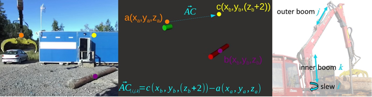
Calculation of control signals is done in the simplest possible way. From the vector calculated between the different positions, x, y and z are simply taken and sent as a signal (rescaled) to each joint, where z manipulates the boom, y manipulates the stick and x swings the entire crane. Due to the speed of the system, this works despite the fact that each signal generates both desired and unwanted movements. For example, if the crane is to be moved outwards, it will also be moved vertically. The system sees this very quickly and adjusts the height, which gives a rather smooth crane movement to the eye.
Tests
Two tests were conducted to evaluate the autonomous timber cranes system:
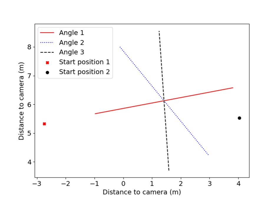
1. Measurement of accuracy and repeatability
The autonomous timber cranes had to start from two positions and move to a point above the log several times. The final position was measured for each test and the test was carried out with the log turned at three different angles as shown in the figure below.
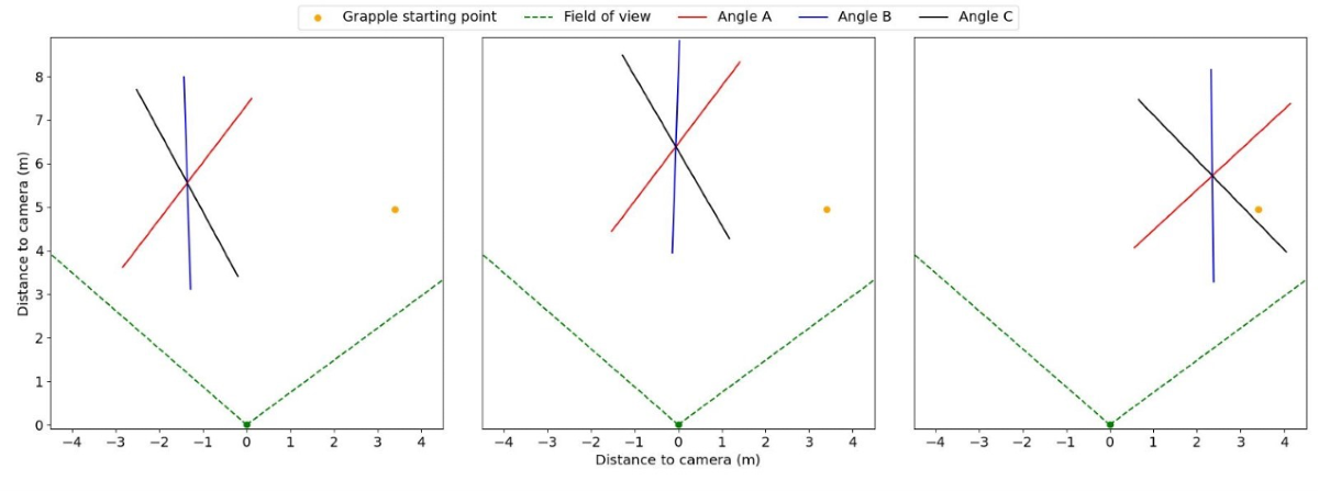
2. Practical evaluation of how well the system can pick up a log
The log was placed in three different positions at three different angles. The node was run and for a successful test, the grapple must have gone again under the log and the grapple’s position must be at least 25 percent from the end of the log.
Result
Test 1
The results showed high repeatability with an average distance of less than ten cm from the mean position. Small systematic deviations were observed depending on the angle of the log, but these were considered to be too small to affect the success rate if the system had been allowed to continue and also grip the log.
Test 2
The system managed to grab and lift the logs in 82 percent of the attempts. Of the unsuccessful attempts, some were due to the system not being able to determine the position of the log, while others failed as the grapple had to be placed in a position where both bolts were not visible to the camera, which meant that the angle of the grapple could not be calculated by the system.
Discussion
The results show that a camera can be used as the only sensor to grip logs on the ground with a full-scale forwarder. The system showed a high repeatability and sufficient accuracy, although with some limitations. In the position where the grapple must be turned so that it ends up in line from the camera, the bolts are not visible and the angle cannot be calculated using this method. However, this problem could easily be avoided by moving the machine a little.
The advantages of this method are that it does not require signals from other systems or sensors, making it easy to mount on almost any type of machine. The only thing that needs to be done is to calibrate the size of the control signals. By using only one sensor, it also does not matter if the camera should get out of its position, as both crane position and log position are measured by the same sensor. Therefore, it is only a coordinate system to keep track of. The impact of any measurement errors is also less, as these errors affect the position of both objects.
Conclusion
This study shows that it is possible to grab logs from the ground with a forestry crane by using only a camera as a sensor.
Forest Machine Magazine is written and edited by a forest professional with over 40 years hands on experience. We are dedicated to keeping you informed with all the latest news, views and reviews from our industry.
#homeoflogging #writtenbyloggersforloggers #loggingallovertheworld